Overview
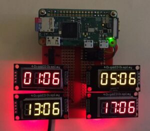
Amateur Radio Operators (aka HAM Radio) use 24 hour UTC (Universal Coordinated Time) for much of their operation. I decided to build a digital clock using the low-cost TM1637 4 digit displays and a Raspberry Pi Zero W instead of just a GUI clock. (Hardware is fun!)
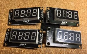
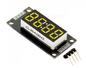
The TM1637 driven display has four 7 segment leds with a center colon “:” between two sets of digits. It requires two wires to drive the display plus 5V + and Ground for a total of 4 wires.
For this particular project, I wanted the Raspi to get its time from NTP (Network Time Protocol) servers via the Internet. I am planning another version of this clock to run on an Arduino Uno and a Real-Time Clock module, for when no WiFi is available and for more portable operation.
I also wanted the clock to show the Local Time in 12hr and 24hr formats as well as UTC in 12hr and 24hr formats. The software is designed to let you use just UTC 24hr (typical hams) or different times on up to 4 different displays.
You can also set the TIME ZONE that you would like to use instead of default Local time. So each of the four displays could show a different time zone and in 12hr or 24hr format.
This project does require soldering connectors or wires onto the Pi and/or the tm1637 modules.
Instructable Ciscuits https://www.instructables.com/Raspberry-Pi-Amateur-Radio-Digital-Clock/
Full instructions are also available on GITHUB: https://github.com/rgrokett/RaspiDigiHamClock
Step 1: Requirements
• Raspberry Pi2, 3, or Zero W. (i.e. any pi with the 40 pin header and Ethernet/Wifi)
• 4 – TM1637 4 digit Display modules http://www.dx.com/p/produino-0-36-4-digit-yellow-…
And/or http://www.dx.com/p/produino-0-36-4-digit-yellow-…
NOTE: you can use larger or smaller ones, as long as they are TM1637 compatible.
• Wire harness with 16 wires (each TM1637 needs 4 wires)
• Solderless Breadboard and wires Or
• Solder-able Breadboard & various pin connectors. http://a.co/4lA7auZ
• 8GB MicroSD or larger for Pi
• 5v power supply for Pi.
Step 2: Software Installation
This application uses the easy to useTM1637.py python library written by Tim Waizenegger. (If you want details about the library, check out: https://github.com/timwaizenegger/raspberrypi-exam…)
Did you know?
If you install Raspbian on an SD card using a PC, you can create two files on the card to configure WiFi and SSH access before you boot it on a Raspberry?
For this, assume your SD card is currently mounted as K: on your PC:
1) Install the Raspbian Lite image to the SD.
https://www.raspberrypi.org/software/operating-systems/#raspberry-pi-os-32-bit
2) With notepad, create a file called just “ssh” and use Save As “All files” to K:\ssh
The file can contain anything. It’s the filename that is important. Must NOT be “ssh.txt”!!!
3) With notepad, create a second file called “wpa_supplicant.conf” with following:
<p>ctrl_interface=DIR=/var/run/wpa_supplicant GROUP=netdev<br>update_config=1
 network={
   ssid="mySSID"
   psk="mypassword"
   key_mgmt=WPA-PSK
}</p>
Use Save As “All files” to K:\wpa_supplicant.conf
Again, do not let Notepad change it to “wpa_supplicant.conf.txt”!!
When you boot the Raspberry the first time, Raspbian will look for these and connect to your Wifi. You will have to look on your Router for the IP address, though, since its auto assigned.
Step 3: Software Installation – Pt.2
1. If you haven’t already, install Raspbian Lite version onto a 8GB or larger microSD card. You DO NOT need the GUI version, as this project does not use a monitor or keyboard.
NOTE!: This project requires Python2.7!
https://www.raspberrypi.org/software/operating-systems/#raspberry-pi-os-32-bit
2. You will need to access the Raspberry remotely via SSH. On Windows, you can use PUTTY SSH terminal program. On Mac, just bring up a command terminal window. https://www.putty.org/
3. Insert the microSD card into the Pi and plug in the power now. It will take a few minutes to boot.
4. To remotely log in to your Raspberry Pi, you will need to find its IP address.
You can try: $ ssh pi@raspberrypi.local
(Or from Putty, enter hostname pi@raspberrypi.local Otherwise, you will need to see if your Router will show the IP addresses of your local devices.
Default id/passwd is “pi/raspberry”
Once logged in as pi user:
5. Update your Raspbian:
$ sudo apt update
$ sudo apt upgrade
6. Configure the Raspberry:
$ sudo raspi-config
a. Change User Password
b. Localization Options -> Change Timezone Select your Local Timezone
c. Tab to Finish
7. Install the RaspiDigiHamClock software:
$ cd /home/pi
$ sudo apt update
$ sudo apt install git
$ git clone https://github.com/rgrokett/RaspiDigiHamClock.git
8. Power down your Pi for setting up the hardware
$ shutdown now
After the LED goes off unplug the power
Step 4: Hardware Wiring
You can solder connectors onto the TM1637 modules and the Raspberry Pi (if it doesn’t already have a connector). Before beginning, decide how you want to mount the displays and if you are going to use a breadboard or solder wires directly onto the Pi and display modules.
TM1637 Module Pins
Wiring Note: Some tm1637 modules flip the +5v and GND pins! So may not appear same as the photos.
The TM1637 module is a 4-digit led display module which uses the TM1637 driver chip. It needs only two connections to control the 4-digit 8-segment display. Two other wires feed 5+ volt power and ground.
PIN	DESC<br>
CLK	Clock
DIO	Data In
GND	Ground
5V	+5 volts
<p><em>Some tm1637 modules flip the +5v and GND pins, so check your module’s markings</em></p>
Test each Module
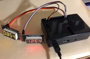
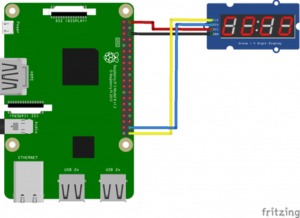
I suggest starting with single 4 wire female connector cable with male connectors soldered to one of the modules and the Pi. Then temporarily connect the first module up to the pins shown below.
TEMPORARY TEST A MODULE<br>TM1637 Module Pin	Pi Physical Pin#
5V			2
GND			6
CLK			40
DIO			38
See the GPIO Diagrams farther down to find the pin layouts.
The second photo shows two displays temporarily wired to a Raspberry Pi 3 with the software running.
1. Once you have a module temporarily wired up and checked your wiring
2. Power up the Raspberry Pi.
The red LED on the Module should light, but there will be NO DISPLAY yet.
3. SSH into your Pi again like previously.
$ cd RaspiDigiHamClock
$ python test.py
You should see the display cycle through various short messages. If you do not, first check your wiring again! It’s easy to flip a wire or plug into the wrong GPIO Pin on the Pi.
If you get a Python error message, verify your Python version using:
$ python -V (capital “V”)
Python 2.7.X
I have not tested against Python 3, so not sure if the library is compatible.
Copy the error message (usually the last line of the error) and Paste into Google search. This may give a clue as to what happened.
If your module works, Congratulations! You know the module and Pi are working. Now repeat for each module to test it. (I suggest shutting down Pi and power off BEFORE plugging/unplugging modules!!)
$ sudo shutdown now
Step 5: GPIO Pins on Raspi
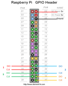
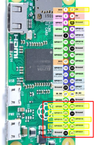
This project uses the GPIO physical BOARD ids for the Pins.
That is Pin 1 to Pin 40. Not the “BCM” GPIO pin numbering. (Yes, bit confusing, but BOARD is just the pin count from top left to bottom right.)
<p>Display Module 	TM1637 Module Pin	Pi Physical Pin#<br>Power			5V					2
Ground			GND				6
</p><p>Module #1		CLK					33
				DIO					31
</p><p>Module #2		CLK					36
				DIO					32
</p><p>Module #3		CLK					37
				DIO					35
</p><p>Module #4		CLK					40
				DIO					38</p>
Note: You do not need to add all 4 modules if desired. You can have between 1 and 4 modules. (Yes, it is possible to go to more modules, but you need to alter the code to support more.)
–> BUT, you MUST plug in the modules sequentially starting at Module #1
This is because the TM1637 library expects a ACK from the module so appears to hang waiting otherwise.
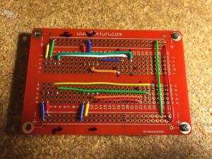
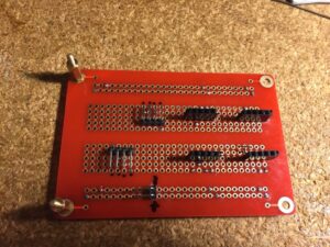
Sample photos of Soldered Breadboard
You need to follow your own wiring pattern to match the GPIO pins shown previously, since the connectors and modules I used may not match yours.
Step 6: Testing!
Wow, that was a bit of wiring! Now time for smoke testing…
Since you already know the individual modules and Pi work (you did test the modules as described previously?), then the next step is to set up the .INI file and run the clock program:
1. Edit the raspiclock.ini
$ cd /home/pi/RaspiDigiHamClock
$ nano raspiclock.ini
2. Change the num_modules to how many you have wired up. This is important as the library will hang waiting for an ACK if it cannot talk to a module. Be sure to wire in the number of modules, IN THE ORDER SHOWN in the .INI Note: Extra TZ and HR and GPIO PINS are ignored if num_modules is less than 4.
3. Add Timezones for each module.
This is Linux TZ Names, like ‘America/New_York’, EST5EDT, UTC, or ‘Local’ for your local timezone as set via raspi-config. The default is UTC
4. Set whether to display 12hr or 24hr mode for each module
<p>[CLOCK]<br>; Number of TM1637 Modules (between 1 and 4) num_modules = 2</p><p>; Time Zones for each Module ; Use raspi-config to set Local timezone ; Default is UTC ; Format is Linux TZ names or ‘Local’ for local time ; ‘America/New_York’, EST5EDT, UTC, ‘Local’ TZ1 = Local TZ2 = UTC TZ3 = TZ4 =</p><p>; 12/24 Hour for each Module HR1 = 12 HR2 = 24 HR3 = 12 HR4 = 24</p><p>; BRIGHTNESS (range 1..7) LUM = 1</p>
5. You should not have to edit the GPIO pins unless you plug them into different pin #’s on the Pi.
6. Save the changes and then run the clock:
$ python raspiclock.py
If all is well, all of your display modules should light up with the times as set up in the .INI file.
Congratulations! Skip the troubleshooting and go to the Final Install…
Step 7: Troubleshooting
You should see some simple debug messages appear:
<p>Initializing...<br>Number of modules = 4
Starting clock loop...
Module#1
displayTM()
Module#2
displayTM()
Module#3
displayTM()
Module#4
displayTM()
(repeating…)</p>
If you tested the modules previously and they all worked, then you know the modules and Raspberry are good.
A) HANG – If the debug messages appear to hang at one spot, the program is waiting for an ACK from that module#.
First check your wiring! It’s easy to flip a wire or plug into the wrong GPIO Pin on the Pi.
Second, swap modules to see if a module suddenly went bad.
Third, check the raspiclock.ini file for errors. If necessary, delete the entire directory and do another GIT CLONE to retrieve again.
Fourth, check your wiring again! 😉
B) If you get a Python error message, verify your Python version using:
$ python -V (capital “V”)
Python 2.7.X
I have not tested against Python 3, so not sure if the library is compatible. Copy the error message (usually the last line of the error) and Paste into Google search. This may give a clue as to what happened.
Step 8: Final Installation
1. Edit the .INI file again and set debug = 0.
$ cd /home/pi/RaspiDigiHamClock
$ nano raspiclock.ini
2. Also verify the TZ timezones and HR 12/24 hour settings are as you desire.
3. Set the Brightness as desired between 1 and 7.
4. Run the install.sh script to add to pi crontab for automatic startup on boot.
$ sh install.sh
5. Reboot
$ sudo reboot
6. It should reboot and then come up running.
FINISHED!