Tape Measure Beam Optimized For Radio Direction Finding
Description
This antenna evolved during my search for a beam with a really great front-to-back ratio to use in hidden transmitter hunts. This design exhibits a very clean pattern and is perfect for RDF use. It trades a bit of forward gain in exchange for a very deep notch in the pattern toward the rear. (You could optimize the design for more forward gain, but at the expense of a really good notch in the pattern toward the rear.) It is a design that can be constructed using only simple hand tools (no machine shop needed) and still perform well. It has been duplicated several dozen times by other local hams and has been successfully used as a club construction project.
When I designed this antenna I had one basic idea in mind. It had to be easy to get in and out of the car when hunting for a hidden transmitter. This would be accomplished by the use of steel “tape measure” elements. These elements could fold easily when fitting the antenna into my car and yet still be self supporting. I decided to use three elements to keep the boom from getting too long.
Another of my design goals was to use materials that were easy to obtain. I chose to use Schedule-40 PVC pipe and fittings available at my local hardware store for the boom and element supports. These kept the cost for the antenna very low. The element supports consist of PVC crosses and tees.
Since I had never seen any plans for an antenna using elements made from 1 inch wide steel “tape measure,” I had to do the design myself. To assist in the design I used a shareware computer aided yagi design program written by Paul McMahon VK3DIP. It allowed me to optimize the antenna for the cleanest pattern combined with the best front-to-back ratio.
| Performance Predicted by YAGI-CAD | |
| GAIN | 7.3 dBd |
| Front-to-Back Ratio | >50 db |
| 3 db Beamwidth | E = 67.5 degrees |
| 3 db Beamwidth | H = 110 degrees |
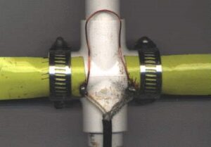
Stainless steel hose clamps are used to attach the driven element halves to the PVC cross which acts as its support. This has the added benefit of allowing you to fine tune your antenna for lowest SWR simply by loosening the hose clamps and sliding the halves of the driven element either closer or further apart. By using the dimensions specified, I found that the SWR was 1:1 at 146.565 Mhz (our Fox-Hunt frequency) when the two elements were spaced approximately 1 inch apart. Figure 1 shows the method used to attach the driven element to the PVC cross.
I used 1 1/2 inch hose clamps to attach all the elements on my prototype beam. Others who have duplicated my design have used self tapping screws to attach the elements to the PVC crosses and tees. Performance is the same using either method. The screws are much less expensive but they do not hold the elements as securely. If you do not use 1/2 inch PVC fittings but instead use 3/4 inch, make sure the hose clamps you buy are large enough to fit.
If you wish a slightly neater looking beam, use the self tapping screws. If you do not mind spending a few more dollars for the hose clamps, use them instead. If I were to build another beam I would use screws for the director and reflector, and hose clamps for the driven element. That would give me the best of both methods.
Rubber faucet washers have been used by some builders between the tape measure element and the PVC fittings on the director and reflector. These allow for the tape to fit the contour of the PVC fitting and will make the antenna look better. Now you know what to do with those washers left over from the assortment you once purchased; You know the ones I mean, the washers that do not fit the faucets you have in your house. If you are an apartment dweller, ask around, these things are stashed in almost every homeowners basement or garage.
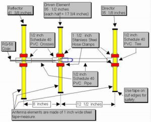
Cut a length of tape measure to 41 3/8 inches. It will be the Reflector element. Cut two lengths of tape measure to 17 3/4 inches. These will be used for the Driven element. Cut one length of tape measure to 35 1/8 inches. It will be used for the Director. Once you have cut the tape measure to length, put vinyl tape on the cut ends to protect yourself from the sharp edges. You will want to scrape or sand off the paint from one end of each of the driven element halves so you can make a good electrical connection to the feedline.
If you are planning to solder the feedline to the driven elements it is best to tin the elements first before attaching them to the PVC cross. If you don’t, the PVC will melt as you apply heat to the element. It would be a good idea to also take the time to form the wire used for the hairpin match into a “U” shape with the two legs of the “U” about 3/4 inch apart. Tin the ends of the hairpin if you plan on soldering it to the driven element. If you tin 1/4 inch of each end of the hairpin it will leave 4 1/2 inches to shape into the “U”.
You will need to cut two lengths of PVC pipe to use as the boom. One should be cut to 11 1/2 inches. It is used to form the boom between the Director and the driven element. The other piece of PVC should be cut to 7 inches. It will be used between the Reflector and the Driven element. Just about any saw will cut through the soft PVC pipe. I used a hacksaw. When we mass produced this antenna as a club project, we marked the pipe and used a portable jig saw to cut the lengths in assembly line fashion. It took longer to measure the pipe than to actually make the cuts. Since the pipe is available in ten foot lengths, you can make a few beams from a single 10 foot length. In any case, you might want to cut a few extras lengths for your friends. They will want to duplicate this once they see your completed antenna.
At this time you can pre-assemble the PVC boom, crosses and tee which will support the tape measure elements. I did not use any cement or glue when I assembled mine. The PVC pipe is secured in the fittings with a friction fit.
The hose clamps I used are stainless steel and have a worm-drive screw which is used to tighten them. They are about 1/2 inch wide and are adjustable from 11/16 inch to 1 1/2 inch diameter. Attach the tape measure elements to the PVC fittings as shown in the accompanying drawing. It is normal for the Reflector and Director elements to buckle a bit as it is tightened to the PVC Tee and Cross. You can eliminate this buckle if you use the washers and self tapping screws to attach these elements instead of the hose clamps. I do not think the beam will withstand as rough a treatment as when hose clamps are used.
How does it perform?
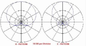
Once you have completed your beam you probably will be interested to see if it performs as well as the computer predicted. The SWR should be less than 2:1 across the entire two meter band. The front-to-back ratio is predicted to be very good with the antenna exhibiting a very deep notch in its pattern towards the rear. The YagiCad 4.1 program produced these antenna pattern graphs showing the pattern you should expect. If you would like to experiment a bit with this program, the yagi specification file for this tape measure beam is available for download here. Simply download the YAGI-CAD program and put the tape measure beam design file in the same directory. You will then be able to experiment with the design.
Note: under Windows95, only the first .yag file will show in the OPEN-FILE menu. You can either move all the other .yag files to a sub-directory or re-start the computer in MS-DOS mode. It works fine there. (I really do not know why this occurs but will blame Microsoft)
Summary
This beam has been used on Fox-Hunts, on mountain tops, at local public service events, outdoors, indoors in attics, just about everywhere. The SWR is typically very close to 1:1 once adjusted. Front to back performance is exactly as predicted. The null in the rear of the pattern is perfect for transmitter hunts. When tested using a sensitive field strength meter and a low powered fox transmitter, full scale readings were seen from a distance of ten feet. With the same field strength meter I was able to point the antenna away from the transmitter and move the reflector element to within a few inches of the transmitter antenna and still not see a reading. I don’t have the facilities to verify a 50 db notch as predicted by the Yagi-Cad software but It sure seems close. The flexible elements have taken a lot of abuse. My antenna has seen a lot of use and has held up quite well. Best of all, when on a fox-hunt, this beam is a breeze to get in or out of the car.
Reference: http://theleggios.net/wb2hol/projects/rdf/tape_bm.htm